


Firmware
Module firmware update_autocom_16Mhz
Module firmware update_autocom_26Mhz
Pictures
Board1_Wiring_diagram.png
Board2_installed.JPG
Board2_Wiring_diagram.png
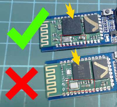
Fake_vs_good.jpg
Software
Blue Suite
FTDI driver
Zadig driver_installer
Please read this entirely before making the procedure. Do it at your own risk.
You will find pictures of the installation in the Pictures folder.
In this folder you will also find the pictures of the fake HC05/HC06. The fake ones will NOT work!!
Please follow this great tutorial showing how to flash a new firmware to the HC05/HC06 module:
https://www.instructables.com/id/Upgrad ... ID-Firmwa/
You should NOT follow the steps for backing up the settings and merge the settings. You should skip them entirely. You will NOT need to use the PSTool software.
All the software needed are provided inside the software folder.
Of course you will not flash the HID firmware, you will flash the firmware provided Firmware folder(there are 2 files for module, you must keep these files together in the same folder). The BlueFlash Tool will ask you for just one file, but it needs the other one inside the same folder in order to flash properly.
Pay attention to the oscillator frequency of your module and flash the firmware that matches yours.
After you flashed the correct flash file for your module, you just need to solder it to the Autocom board. Follow the picture that matches your CDP board.
Beware that the Arduino module can handle 5V power supply as it has a 3.3v regulator built in. If you use the module WITHOUT the 3.3v regulator, you should pick the 3.3V from the Autocom Board, as shown in the pictures. Pay attention to the correct CDP board version that matches yours as the connection points are different for each board.
Section téléchargement, voir en bas de cette page
Download section, see bottom of this page


